
Where Does the SD119A99P3 Linear Solenoid Fit in Automated Equipment?
What Makes the SD119A99P3 Linear Solenoid a Practical Actuation Solution?
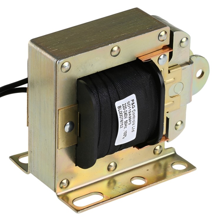
Where industrial equipment requires a straightforward pulling movement, the SD119A99P3 Linear Solenoid provides a compact electromechanical solution powered by a 240 V AC supply. As part of the broader Linear Solenoids category, it converts electrical energy into controlled linear movement for operating latches, levers, releases and other mechanical assemblies.
Manufactured by Mechetronics, this pull-action AC laminated solenoid combines a maximum stroke of 34.2 mm with a specified magnetic force of 3.6 N. Its 100% duty-cycle rating makes it suitable for applications where the coil may remain energised for extended periods, provided that it is installed correctly and operated within its specified electrical and environmental limits.
What Are the Main Technical Specifications?
The SD119A99P3 Linear Solenoid is designed around a laminated AC magnetic structure. When 240 V AC is applied to the coil, the magnetic field draws the movable plunger towards its seated position. The resulting motion can be transferred to a linked mechanical part.
Its principal specifications include:
- Manufacturer part number: SD119A99P3
- Operating action: Pull
- Supply voltage: 240 V AC
- Maximum stroke: 34.2 mm
- Magnetic force: 3.6 N
- Continuous power rating: 28 VA
- Duty cycle: 100%
- Overall dimensions: 66.2 × 60.5 × 36.7 mm
- Approximate weight: 1.1 kg
- Environmental compliance: RoHS compliant
These figures allow engineers to evaluate the available installation space, required movement, electrical load and mechanical demand before incorporating the actuator into a machine.
How Should Its Stroke and Pulling Force Be Evaluated?
The maximum 34.2 mm stroke describes the available plunger travel, but the mechanism should not automatically be designed to use every millimetre. Allowance may be necessary for mounting tolerances, wear and the correct seating of the plunger. A linkage that prevents complete seating can cause excessive vibration, buzzing, or a rise in temperature.
The 3.6 N force rating must also be compared with the actual load under operating conditions. Friction, return springs, linkage angles and gravity can increase the force required at the solenoid. A practical design should include an appropriate engineering margin instead of matching the actuator to the theoretical load exactly.
For operations that require a deliberate energising period or delayed release, suitable Timer Relays can introduce controlled timing while keeping the actuation sequence repeatable. The timer and switching components must be compatible with the control voltage, inductive load and required operating sequence.
What Does the 100% Duty-Cycle Rating Mean?
A 100% duty-cycle rating means the SD119A99P3 Linear Solenoid is intended to tolerate continuous energisation under its specified conditions. This can benefit holding applications where the plunger must remain pulled in for longer than a short pulse.
However, continuous-duty capability does not remove the need for thermal planning. Ventilation, ambient temperature, mounting surfaces and nearby heat-producing equipment can influence operating temperature. Designers should prevent heat-sensitive wiring or plastic parts from touching the solenoid body and confirm that the completed assembly remains within acceptable limits.
AC solenoids can also draw higher current while the plunger is moving and the air gap is open. The selected switching device should therefore be rated for an inductive AC load and its associated inrush, rather than being chosen only from the 28 VA continuous rating.
How Can It Be Integrated into a Control Panel?
Reliable integration begins with organised wiring, correct conductor sizing and appropriate circuit protection. Inside a control cabinet, DIN Rail Terminal Blocks can provide clearly identified connection points for the solenoid supply and control conductors. This arrangement can simplify inspection, testing and future replacement.
The solenoid should be switched through a suitably rated relay, contact or control output. Protective devices must be selected according to the installation, prospective fault current and manufacturer guidance. Where switching transients could disturb neighbouring control electronics, an appropriate suppression method may be considered, but it must be suitable for a 240 V AC inductive circuit.
Installation should be completed by a competent person. The supply must be isolated, locked off where required and proven dead before wiring, adjustment or mechanical maintenance begins.
How Should Machine Safety and Status Indication Be Planned?
If the SD119A99P3 Linear Solenoid is fitted to industrial machinery, its movement must be considered within the machine’s complete risk assessment. Properly selected Emergency Stop Push Buttons may form part of a separately engineered safety system, while Panel Mount LED Indicators can communicate energised, released or fault conditions to operators.
The solenoid itself should not be assumed to provide a safety-rated locking or interlocking function unless the completed system has been specifically designed and validated for that purpose. An emergency-stop circuit should be assessed independently and should not rely solely on an ordinary control component to achieve a safe state.
Which Applications Can Benefit from This Solenoid?
The SD119A99P3 Linear Solenoid is particularly relevant where electrical control must produce a single, repeatable pulling action. Potential applications include:
- Mechanical latch release systems
- Automated gates and access mechanisms
- Packaging and material-handling equipment
- Sorting and dispensing machinery
- Industrial shutters or mechanical stops
- Cabinet and equipment release mechanisms
- Process machinery requiring a controlled pull action
Its suitability depends on more than supply voltage. Engineers should verify the necessary stroke, load direction, return method, operating frequency, ambient conditions and available mounting space. Side loading should be minimised because it can increase friction and accelerate plunger wear.
How Can Reliable Operation Be Maintained?
Correct alignment is essential. The plunger should travel freely without rubbing against surrounding structures, and the linked mechanism should not introduce unnecessary lateral force. Fasteners should remain secure, while the moving assembly should be checked periodically for contamination, wear or mechanical obstruction.
Unusual buzzing can indicate incomplete plunger seating, misalignment, low supply voltage or debris within the mechanism. Excessive heating may result from a persistent air gap, restricted ventilation or an unsuitable electrical supply. Investigating these symptoms promptly can prevent damage to the coil and connected mechanism.
With suitable load assessment, safe mains wiring and accurate mechanical installation, the SD119A99P3 Linear Solenoid offers a focused solution for converting a 240 V AC control signal into dependable pull-action movement.